The alternator is a critical component in a vehicle’s electrical system, responsible for generating electrical power to recharge the battery and power various electrical components while the engine is running. Understanding the wiring diagram of an alternator is fundamental for mechanics, automotive enthusiasts, and anyone involved in electrical troubleshooting. This article aims to demystify the complexities wiring diagram of alternator, shedding light on their components and functionalities.
Decoding the Basics:
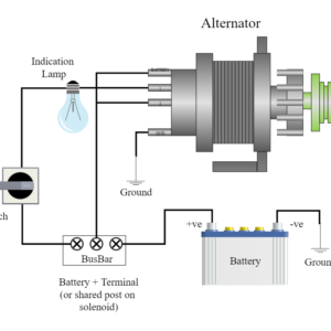
An alternator wiring diagram illustrates the connections and pathways of various electrical components within the alternator system. At its core, an alternator consists of several key parts: the rotor, stator, diode rectifier assembly, voltage regulator, and output terminal. These components work in harmony to produce and regulate electrical power.
Wiring Configuration:
The wiring diagram outlines the connection points for these components. The rotor, typically connected to the battery through an ignition switch, produces a rotating magnetic field when the engine is running. This field induces an alternating current (AC) in the stator windings.
The AC produced in the stator windings is then converted into direct current (DC) by the diode rectifier assembly. This assembly consists of diodes arranged in a specific configuration to ensure that the current flows only in one direction, enabling the conversion from AC to DC.
The voltage regulator, a crucial part of the alternator system, monitors the electrical output. It adjusts the field current in the rotor to control the alternator’s output voltage. This regulation is essential to prevent overcharging or undercharging of the battery, optimizing its lifespan and performance.
Diagram Components and Symbols:
Alternator wiring diagrams use standardized symbols to represent various components and connections. Common symbols include lines indicating wires, arrows denoting the direction of current flow, and specific shapes representing diodes, resistors, and other electrical elements. Understanding these symbols is vital for interpreting the diagram accurately.
Troubleshooting and Maintenance:
A clear understanding of the alternator wiring diagram is invaluable when diagnosing electrical issues in a vehicle. By following the diagram and using a multimeter to test connections and voltage levels, mechanics can pinpoint faulty components or wiring problems. This knowledge also aids in performing regular maintenance, such as checking connections for corrosion and ensuring proper grounding.
Conclusion:
Mastering the intricacies of a wiring diagram of alternator is essential for anyone involved in automotive maintenance or repair. These diagrams serve as roadmaps, guiding technicians through the complex network of electrical connections within the alternator system. With a comprehensive understanding of these diagrams, diagnosing issues and performing effective repairs becomes more accessible, ensuring optimal performance of the vehicle’s electrical system.